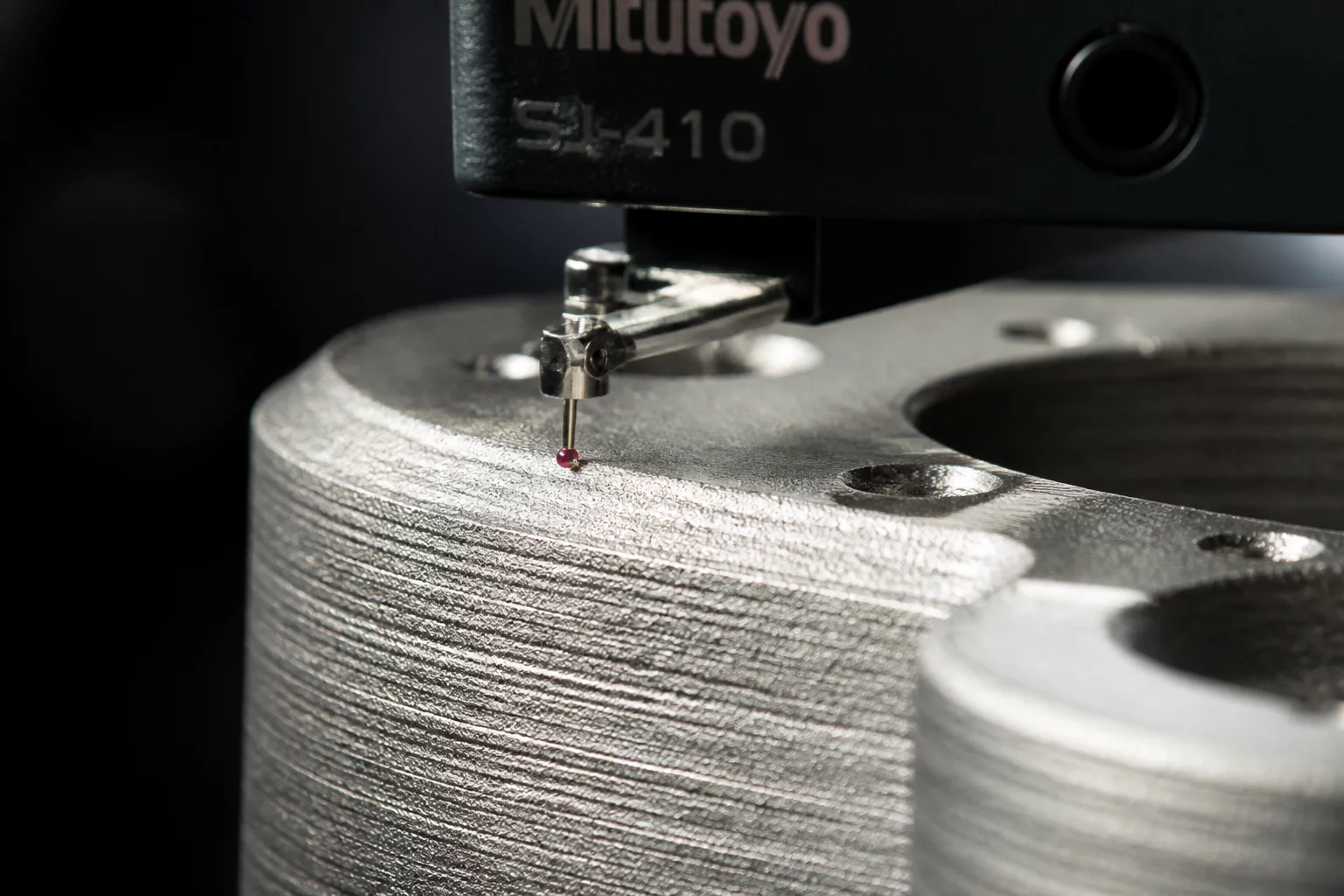
Surface roughness in additive manufacturing (AM) is more than just a cosmetic concern; it is a critical functional parameter that dictates how a part interacts with its environment. Whether it is the sliding friction of a piston, the sealing capability of a gasket surface, or the fatigue resistance of a structural beam, the texture of the surface can make or break the component's utility. Establishing functional limits means moving beyond "it looks rough" to "it measures X, which is unacceptable for Y reason."
Why Roughness Limits Matter
In many AM processes, particularly those involving powders or layers, a certain level of inherent roughness is expected. However, when these values exceed specific thresholds, they can lead to accelerated wear, poor fitment, or even structural failure due to stress concentrations. It is vital to define what is "good enough" for the specific application rather than aiming for perfection, which often increases cost without adding functional value.
Critical Parameters for Evaluation
When we talk about surface roughness, we usually look at several key metrics. Using a profilometer, as seen in the primary analysis, allows us to quantify the following:
- Ra (Arithmetic Average): The most common metric, representing the average height of peaks and valleys across the surface.
- Rz (Maximum Height): The distance between the highest peak and the lowest valley within a sampling length, critical for sealing applications.
- Surface Pattern: The orientation of the layer lines relative to the direction of motion or stress.
Setting the Acceptance Threshold
Determining a limit requires understanding the part's role. A static bracket might tolerate an Ra of 15 µm, while a bearing surface might require post-processing to reach an Ra of 0.8 µm. When reviewing parts, we should categorize thresholds based on the following functional impacts:
Aerodynamic drag in fluid channels, fluid sealing integrity in pressurized systems, and stress concentration points in high-load structural parts. If a part's roughness exceeds the pre-defined limit, it should be moved to a "Review Again" or "Post-Process" category rather than being immediately rejected, as surface finish is often one of the few AM defects that can be corrected after printing.
Inspection Protocol
It is recommended to inspect at least three different zones of an AM part: the bottom surface (build plate interface), the side walls (layer interface), and any slanted surfaces where the "stair-stepping" effect is most prominent. By capturing data from these varied orientations, you can ensure that the functional limits are met across the entire geometry, not just in the most favorable areas.